3D X-Ray Machine for Electronics: Use-Case Overview
How 3D X-ray machines are used in electronics inspection, what buyers should evaluate, and where glasses-free 3D display workflows fit alongside CT-based NDT review.
3D X-Ray Machine for Electronics: Use-Case Overview
A 3D X-ray machine for electronics is an inspection system that uses X-ray computed tomography (CT) to produce volumetric, three-dimensional images of electronic components, assemblies, and devices. Instead of a single 2D projection, the system reconstructs cross-sectional slices and 3D models that reveal internal structures such as solder joints, bond wires, vias, and hidden layers. These systems are widely used in failure analysis, quality assurance, and non-destructive testing (NDT) for electronics.
This article is an objective, third-party use-case overview. It does not rank specific products or vendors and does not quote pricing, as both vary significantly by configuration and region.
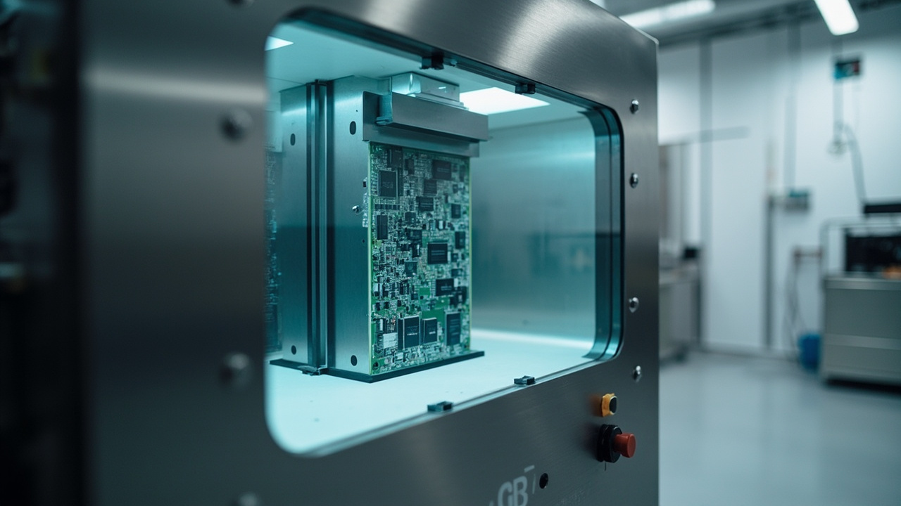
A typical 3D X-ray inspection setup for electronics, combining an X-ray source, detector, and precision sample stage.
What a 3D X-ray machine for electronics actually is
A 3D X-ray system for electronics is essentially a micro-focus or nano-focus X-ray source combined with a high-resolution detector and a precision sample manipulator. The sample is rotated (and in some systems tilted) while multiple 2D projections are captured. Reconstruction software then combines those projections into a volumetric dataset — a stack of cross-sections that can be sliced, rendered, and measured in three dimensions.
The “3D” in the term refers to the reconstructed volumetric dataset, not to the way the image is displayed. The image itself is typically viewed on a standard monitor or, in more advanced review setups, on a stereoscopic or glasses-free 3D display that allows the reviewer to perceive depth directly.
Where 3D X-ray is used in electronics workflows
3D X-ray inspection is most commonly applied in the following electronics scenarios:
- BGA and QFN solder joint inspection — verifying voiding, head-in-pillow defects, and bridging under ball grid array and quad flat no-lead packages.
- Bond wire and die attach verification — checking wire sweep, die placement, and attachment quality in power modules and MEMS devices.
- Multi-layer PCB analysis — examining buried vias, inner-layer alignment, and through-hole barrel fill in complex multilayer boards.
- Failure analysis and root-cause investigation — locating cracks, delamination, and contamination in returned or failed devices.
- Counterfeit and authenticity screening — comparing internal structure of suspect components against known-good reference parts.
- R&D and process development — studying solder reflow behavior, underfill flow, and new package designs during prototyping.

Cross-sectional slice and volumetric rendering of BGA solder joints reconstructed from 3D X-ray projection data.
How 3D X-ray data is produced and reviewed
The imaging chain typically follows these steps:
- Sample placement — the device under test is mounted on a stage that allows rotation and sometimes tilt.
- Projection acquisition — hundreds or thousands of 2D X-ray images are captured at different angles.
- Tomographic reconstruction — software combines the projections into a 3D volume, often using filtered back-projection or iterative algorithms.
- Visualization and measurement — the volume is sliced into cross-sections, rendered as 3D models, or analyzed automatically for defects.
Reviewers interact with this data using specialized software. Common tasks include scrolling through slice stacks, rotating the volume, clipping to expose internal features, and performing virtual cross-sections at arbitrary angles. For defect review meetings, some teams export still images or short animations; others use stereoscopic rendering or glasses-free 3D displays to share the volumetric data with multiple reviewers in the room.
What buyers should evaluate in a 3D X-ray system
Because specifications vary widely and pricing is configuration-dependent, this section focuses on evaluation criteria rather than specific numbers.
- X-ray source type and focal spot size — micro-focus sources (typically a few microns) suit most electronics work; nano-focus sources offer higher detail but may have trade-offs in scan speed and contrast for dense assemblies.
- Voltage range — higher voltage is needed for denser or thicker samples, but lower voltage produces better contrast for low-density features such as aluminum bond wires. A system that covers a broad range is more flexible across component types.
- Detector resolution and pixel size — determines the spatial detail that can be captured. Magnification geometry, not just detector pixel count, drives effective resolution.
- Stage accuracy and travel — precision rotation and tilt stages are important for inspecting tall components or performing oblique views.
- Reconstruction software — algorithms, artifact correction, and ease of use affect both image quality and throughput.
- Throughput and automation — automated inspection routines, sample loading, and recipe management matter in production QA environments.
- Radiation safety and shielding — the system must meet applicable safety standards for the operating environment.
- Service, support, and training — long-term uptime depends on access to qualified service and application support.
Buyers should request demonstrations on representative samples before committing to a configuration.
How a 3D-capable review display fits into the workflow
The 3D X-ray machine produces the volumetric dataset; the display is what the reviewer actually looks at. Most installations rely on a high-quality 2D monitor, but some teams consider a stereoscopic or glasses-free 3D display for shared review of complex volumes. The intent is to let multiple reviewers perceive depth without wearing headsets, which can be useful in collaborative failure-analysis sessions.
Relevant display considerations include:
- Whether the display supports the rendering mode (side-by-side, multi-view, or volumetric rendering) exported by the reconstruction software.
- Whether the team values a shared-viewing, monitor-style workflow over an individual headset workflow.
- How often reviewers switch between detailed 2D measurement work and group discussion of 3D volumes.
Displays such as those in the autostereoscopic and stereoscopic display categories can complement a 3D X-ray system, but they are review-side tools, not inspection tools, and they do not change the underlying CT imaging performance.

Reviewing a reconstructed 3D X-ray volume on a glasses-free 3D display during a collaborative inspection session.
Limitations and uncertainty
This overview is intentionally general. The following points are worth keeping in mind:
- Specifications such as resolution, voltage range, and throughput vary significantly across systems and are not standardized across the industry.
- Pricing depends on configuration, optional software modules, service contracts, and regional factors; no representative figures are provided here.
- Not all components or assemblies are equally suitable for 3D X-ray — very dense or large samples may require specialized systems or higher voltage.
- The term “3D X-ray” is sometimes used loosely for 2D oblique-view X-ray inspection; the discussion above refers specifically to computed tomography that produces volumetric data.
- Vendor and product selection should be based on direct evaluation, sample testing, and reference checks rather than on published rankings.
Next steps for evaluating a system
For teams beginning an evaluation:
- Define the inspection tasks — list the component types, defect modes, and throughput targets that matter most.
- Prepare representative samples — including known-good and known-defective units for benchmarking.
- Request demonstrations — ask vendors to image your samples and review the results in person when possible.
- Evaluate the software workflow — reconstruction speed, artifact handling, and ease of measurement are as important as raw image quality.
- Plan the review environment — consider how the team will discuss findings, and whether a 3D-capable display would add value to collaborative review.
A 3D X-ray machine for electronics is a significant investment. A structured evaluation based on real samples and real workflows will produce better outcomes than a comparison based on specifications alone.
Ready to explore 3D displays?
Browse our detailed comparisons and buying guides to find the right spatial display for your workflow.
View Best 3D MonitorsDisclosure: This article is part of 3DMonitor.net's educational content. Product recommendations are based on research and may contain affiliate links. See our full disclosure.